

How to Read Hydraulic Schematics to Identify Faults Faster
Time : Jul 17, 2026 View : 104
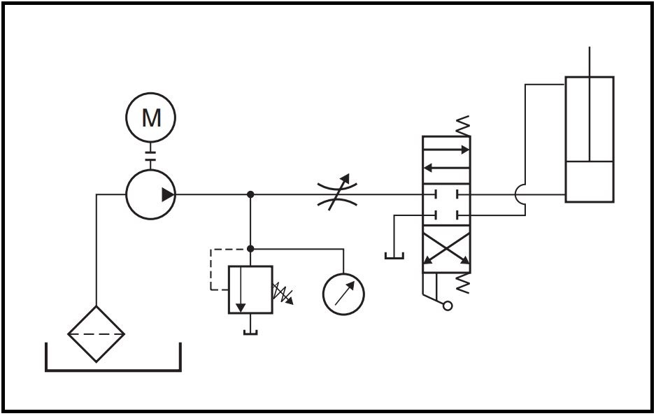
In the tough field of industrial machines, any stoppage hurts output. Technicians and engineers who can read hydraulic schematics well gain a real edge. This skill turns a slow, expensive repair into a quick solution. At KYDAC, we know every strong hydraulic system rests on solid circuit design and well-made parts. This handbook offers a clear way to understand symbols and follow them to find the exact cause of a problem.
Decoding the Blueprint: The Core of Hydraulic Schematics
Hydraulic schematics work like maps that show how power travels through the system with fluid. Learning the basic symbols is the starting point for faster fixes.
Lines and Connections: The Arteries of the System
Lines stand for the hoses and pipes that carry hydraulic oil. The way each line looks tells its job in the circuit.
- Continuous Lines: These show the main lines that move high-pressure fluid to cylinders or motors.
- Dashed Lines: These mark pilot or drain lines that carry control signals or send small leaks back to the tank.
- Enclosure Outlines: A dash-dot box around symbols means they form one unit, like a multi-way Hydraulic Valve block or a pump group.
- Joining Dots: A filled dot where lines meet confirms they connect physically. Lines that cross without a dot stay separate.
Navigating Hydraulic Valve Symbols
The Hydraulic Valve acts as the control center in the drawing. It decides where fluid travels, under what pressure, and how fast. Reading these symbols helps spot if a part fails to shift or manage flow properly.
Directional Control Valve (DCV) Representation
Directional valves appear as several boxes that show the different positions the valve can take.
- Envelopes: The count of boxes shows how many positions exist. A 3-position valve has three boxes, usually with a center neutral spot.
- Flow Paths: Arrows drawn inside the boxes point out the flow direction for each position, for example from P to A and B to T.
- Actuation Methods: Marks on the sides of the boxes explain how the valve moves. A zigzag stands for a spring, a straight line for a lever, or a special shape for a solenoid.

Pressure and Flow Control Symbols
These symbols cover parts that guard against too much pressure or set the speed of motion.
- Relief Valves: Drawn as a closed valve with an arrow leaving the pressure line. It opens to the tank once pressure goes past the spring limit.
- Check Valves: Shown with a ball sitting against a seat, like a circle next to a V. Flow can go only one way.
- Flow Regulators: Usually an opening or narrow spot in the line, sometimes with an arrow to show the rate can change.
Troubleshooting via Schematic Interpretation
When equipment stops working, the schematic lets you look inside without taking things apart. You compare the planned flow on paper to what the machine actually does and narrow down the issue.
The “Trace and Isolate” Strategy
Good troubleshooting means following fluid from the pump to the weak actuator and watching for pressure loss or blocked paths at each point.
- Identify the Actuator: Begin at the cylinder or motor that does not perform right and trace back through the circuit.
- Check the Control Point: Find the specific Hydraulic Valve on the drawing that manages that actuator.
- Test Pilot Signals: For pilot-operated valves, follow the dashed lines to the signal source and make sure it reaches the spool.
KYDAC Engineering: High-Performance Hardware for Your System
With more than 24 years in the business, KYDAC builds the actual parts shown in these drawings. Our items meet international standards such as ISO/TS16949 and work as direct swaps for major names like Rexroth and Vickers.
KYDAC Solenoid Valves: Rapid Response and Reliability
Solenoid directional valves from KYDAC, including the 4WE6 and 4WE10 series, suit automated work and handle pressures up to 35 MPa.
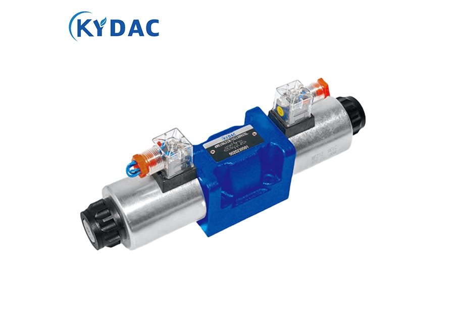
- Fast Response Times: They change position in under 100ms, which fits fast production lines.
- Durability: Bodies come in cast iron or stainless steel to handle shaking and rough conditions.
- Global Compatibility: The valves accept different AC and DC voltages and use standard connections for simple setup.
KYDAC Monoblock and Sectional Valves: Compact Multi-Circuit Control
Mobile machines often have little room. KYDAC supplies many monoblock (P series) and sectional (DCV series) valves that pack several jobs into one piece.
- High Flow Capacity: The DCV140 series manages up to 140 L/min, giving plenty of power for mining and construction gear.
- Leak-Proof Design: Monoblock models like the P80 and P120 use a single casting that removes extra leak spots inside.
- Modular Flexibility: Sectional types let you stack as many as 12 sections to match the needs of big machines such as 1000-ton cranes.
Field-Proven Hydraulic Valve Applications
The worth of a Hydraulic Valve shows up in daily work. KYDAC parts tackle common issues that come up on job sites.
Optimizing Agricultural Silage Balers
Farm work needs good timing. The Green Storage Baling Machine Special Valve Group from KYDAC brings picking, feeding, pressing, and unloading together in one solid unit. This replaces many outside pipes, cuts leak chances, and improves fuel use by 15-25 percent for farmers.
Powering Heavy Construction Equipment
On big construction jobs, handling large loads safely matters most. The DCV100 series sectional valves serve as the main control for large excavators and cranes that perform more than 20 different moves. Load-sensitive control shares flow where it counts, so the boom rises evenly even at full capacity.

Conclusion
Learning to read a hydraulic schematic starts strong maintenance work. Yet solid parts are still needed to carry out the repair. KYDAC delivers National Heavy-Duty Equipment standards in Hydraulic Valves, pumps, and motors so machines follow the original plan. Whether building fresh systems or updating old ones, KYDAC brings 24 years of field-tested knowledge and worldwide trust.
Ready to improve how your system runs? Contact our engineering team today for a custom technical plan and setup details matched to your needs.
FAQ
Q: Why do some lines in a schematic have arrows and others do not?
A: Arrows inside valve symbols indicate the specific flow direction for that position. Arrows on general lines typically indicate a one-way check valve or the intended path of a pilot signal.
Q: Can a KYDAC valve directly replace a brand-name valve in my current schematic?
A: Yes. KYDAC valves are designed with universal mounting surfaces (ISO 4401) and are 100% interchangeable with equivalent models from brands like Yuken, Rexroth, and Vickers.
Q: What does a dash-dot line around a component signify?
A: This indicates that several individual symbols are housed within a single physical component or manifold block, such as a KYDAC monoblock valve assembly.
Q: Why is “load sensing” (LS) important in modern schematics?
A: Load sensing signals allow the pump to only provide the flow and pressure required by the current load. This reduces heat and energy consumption, often saving 15%-30% in fuel.
Related News
Leave a Message
If you are interested in any product, please contact us. We will introduce our products to you in more detail


