

How Does a Hydraulic Orbital Motor Work in 4 Technical Steps
Time : Jul 24, 2026 View : 101

Heavy machinery depends on turning fluid pressure into strong rotating power. This keeps daily operations running without interruption. At KYDAC, we have worked for many years to refine the parts that drive these systems. Our focus remains on hydraulic valves, gear pumps, and motors built for demanding conditions. Engineers and fleet managers gain an edge when they understand the details of an orbital motor. Such insight supports better reliability and longer equipment life.
Understanding the Internal Architecture of a Hydraulic Orbital Motor
Before diving into the movement, one must understand the robust structural design that allows a hydraulic orbital motor to handle immense pressure while maintaining smooth rotation.
The Core Components that Drive Performance
The internal efficiency of the motor depends on the synergy between the rotor-stator pair and the flow distribution system.
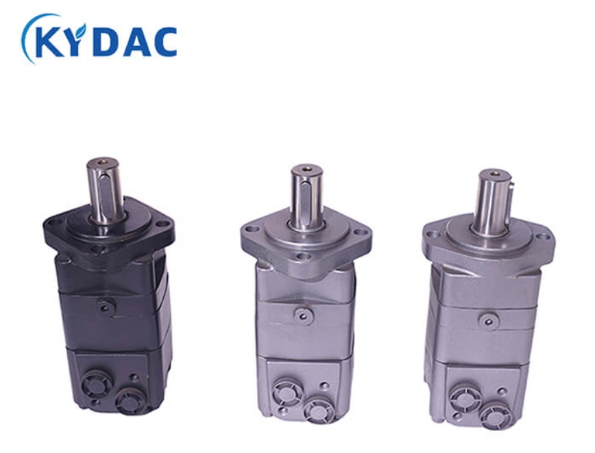
- The Gerotor/Geroler Design: Our BMR serieshydraulic orbital motor utilizes a Geroler design, which features rollers in the stator to reduce friction and improve starting pressure.
- Rotors and Stators: In high-pressure models like the BMT serieshydraulic orbital motor, a column-type rotor and an optimized stator design ensure high volumetric efficiency and a long service life.
- Distribution Valves: Distribution is handled either via a spool valve (common in the BMP series) or an end-face planar flow distribution (featured in the BMS series) for higher precision.
The 4-Step Technical Cycle: How a Hydraulic Orbital Motor Operates
The transformation of hydraulic energy into mechanical work follows a rhythmic, four-stage process within the motor’s chambers.
Step 1: High-Pressure Fluid Intake
The process begins when pressurized hydraulic oil is delivered from a pump, such as a KYDAC 2.5P series gear pump, into the motor’s inlet port.
- Pressure Entry: The fluid enters under high pressure, often reaching up to 35 MPa in heavy-duty systems.
- System Integration: This fluid flow is typically managed by a KYDAC ZT-L12 monoblock valve to ensure the motor receives the exact volume needed for the task.
Step 2: Precision Distribution via Flow Valves
Once inside, the fluid must be directed to specific chambers within the rotor-stator assembly to initiate movement.
- Timing the Flow: The distribution valve (spool or disc) rotates in sync with the output shaft to open and close ports at precisely the right millisecond.
- KYDAC Advantage: In our BMS serieshydraulic orbital motor, advanced end-face flow distribution ensures high accuracy and robust wear compensation, preventing internal leakage.
Step 3: The Eccentric Orbital Movement
This is the defining characteristic of a hydraulic orbital motor, where the rotor does not just spin; it “orbits” within the stator.
- Eccentric Path: The rotor has one less tooth than the stator, causing it to roll around the internal circumference of the stator.
- Volume Expansion: As the high-pressure fluid fills the expanding chambers on one side, it forces the rotor to move, creating a powerful rotating motion.
Step 4: Mechanical Torque Output and Exhaust
In the final step, the orbital movement of the rotor is converted into a steady rotation of the output shaft, while used fluid is expelled.
- Torque Transfer: A high-strength linkage shaft connects the orbiting rotor to the output shaft, providing the mechanical power needed to turn wheels or gears.
- Fluid Return: The low-pressure fluid is pushed out of the contracting chambers and directed back to the reservoir through the return line.
KYDAC Engineering: Choosing the Right Hydraulic Orbital Motor
Not all motors are built equal, and at KYDAC, we categorize our products based on the specific load and environmental demands of our global clients.
High-Load Solutions with the BMT Series
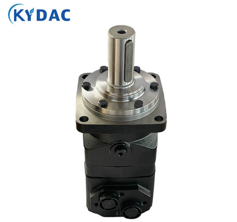
When your application requires maximum power and the ability to withstand significant radial forces, the BMT series hydraulic orbital motor is the industry benchmark.
- Tapered Roller Bearings: This series features a tapered roller bearing structure that enhances radial load capacity, allowing the motor to directly drive heavy working mechanisms.
- Output Capacity: With displacement models like the BMT500 delivering up to 1063 Nm of torque, it is designed for the most grueling industrial environments.
Efficiency in Compact Spaces with the BMS and BMM Series
For machinery where installation space is at a premium but high power-to-weight ratios are required, we provide compact cycloidal solutions.
- BMM SeriesHydraulic Orbital Motor: This is our smallest configuration, using shaft distribution flow to deliver high power in a very low-weight package, ideal for small automation units.
- BMS SeriesHydraulic Orbital Motor: Offering a balance of high working pressure and longevity, the BMS series is widely used where consistent speed and load characteristics are critical.
Where KYDAC Orbital Motors Drive Industrial Power
A hydraulic orbital motor is only as good as the problem it solves in the field. KYDAC components are engineered to address specific mechanical challenges.
Optimizing Agricultural Harvesting Equipment
Agricultural machinery often faces varying crop densities that can stall standard motors or cause inconsistent processing.
- The Solution: By integrating the BMR series with our Green Storage Baling Machine Special Valve Group, we ensure that silage balers maintain constant torque even under heavy loads.
- Result: This prevents equipment downtime during peak harvest seasons and improves the density and quality of the bales produced.

Enhancing Stability in Aerial Work Platforms
In material handling and high-altitude platforms, jerky movements can be dangerous and inefficient.
- The Solution: Our BMER series features needle-toothed rotor-stator pairs and high-pressure oil seals that provide incredibly smooth low-speed rotation.
- Result: This solves the problem of “stick-slip” motion, allowing operators to position platforms with millimeter precision, even at extreme heights.
Elevate Your Machinery with KYDAC
At KYDAC, we don’t just supply parts; we provide integrated hydraulic solutions backed by 24 years of research and a professional team of 30 technical engineers. Whether you are an OEM manufacturer looking for a reliable supply chain or an engineering firm needing customized performance, our hydraulic orbital motor lineup is designed to exceed your expectations.
Ready to optimize your hydraulic system? Contact our expert team today to discuss your technical specifications and receive a tailored quote for your next project.
- Email: Maria@shangjiayeya.com
- WhatsApp: +86 15830130792
FAQ
Q: What is the main difference between a Gerotor and a Geroler motor?
A: A Gerotor has its rotor roll right against the stator. A Geroler, such as the KYDAC BMR, places rollers inside the stator. This setup cuts friction and lifts mechanical efficiency in daily use.
Q: Why do some hydraulic orbital motors have a case drain port?
A: The case drain port sends internal leakage straight back to the tank. It shields the shaft seals from high backpressure. This feature proves useful in parallel or series motor setups where pressure can build up fast.
Q: Can a hydraulic orbital motor handle high radial loads directly?
A: Yes, when fitted with tapered roller bearings. The BMT series uses this bearing layout on purpose. It lets the motor connect straight to heavy wheels or gears without extra support.
Q: How do I choose the correct displacement for my motor?
A: Displacement sets both torque and speed. The BMT800, with its larger size, delivers strong torque at slower speeds. The BMM8, smaller in comparison, turns faster and fits lighter jobs where quick motion matters most.
Leave a Message
If you are interested in any product, please contact us. We will introduce our products to you in more detail


